This guide explains how to install, connect, use, and troubleshoot the Morpho UV Printer External Exhaust System. Watch the complete installation wiki before starting, then follow the illustrated steps in order.
The External Exhaust System removes air from the printer's print chamber and routes it to a compatible filtration unit or an approved exhaust path. It can provide an additional odor-control option, but it does not guarantee complete odor or emission removal. Follow the instructions for the connected fan or filtration unit and all applicable local requirements.
Important
The External Exhaust System changes the airflow around the printer. Excessive airflow can affect UV ink droplet trajectory and print quality. Do not install or operate the system until the connected fan or filtration unit, hose size, airflow range, and exhaust destination have been confirmed as compatible.
¶ External Exhaust System Overview
The available 3D-printable parts are listed below. Use the exact file name shown in the download link when preparing a model.
| Model | Intended use | Download |
|---|---|---|
| Side cover model | Side-cover configuration for an external exhaust connection. | side_cover.stp |
| Straight exhaust cover model | Direct connection to a 63.5 mm (2.5 in) duct. | straight_exhaust_cover_new_shap |
| Hose adapter model | Connection from a 63.5 mm (2.5 in) duct to a 100 mm (4 in) duct. | hose_adapter_2.5_inch_to_4_inch |
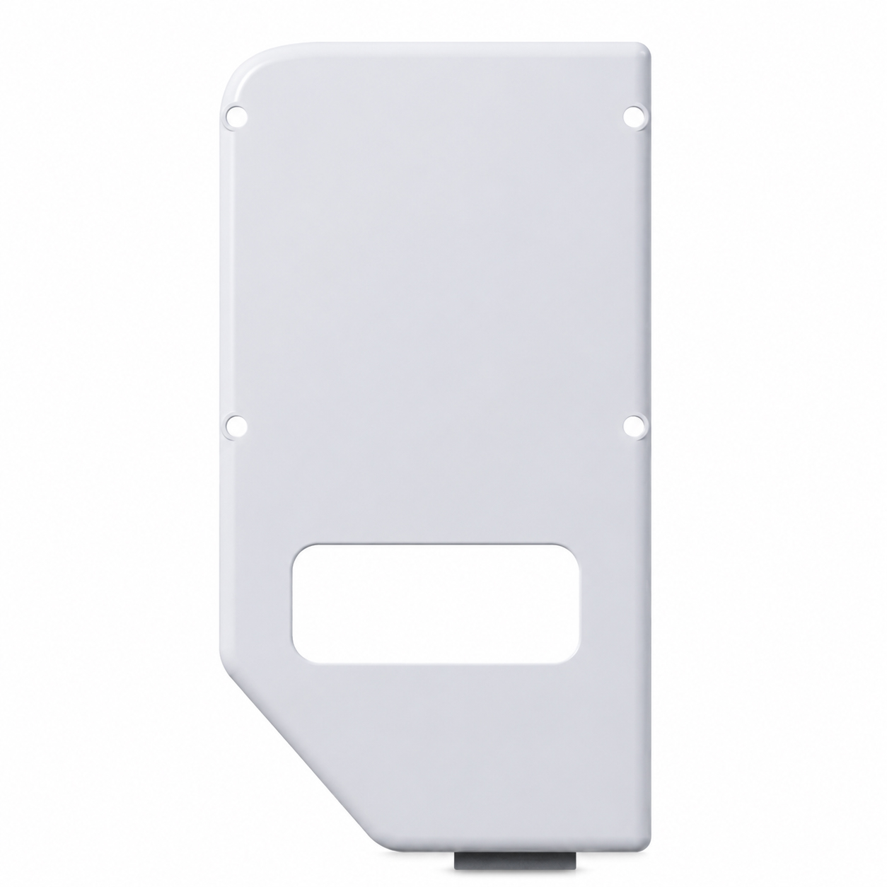
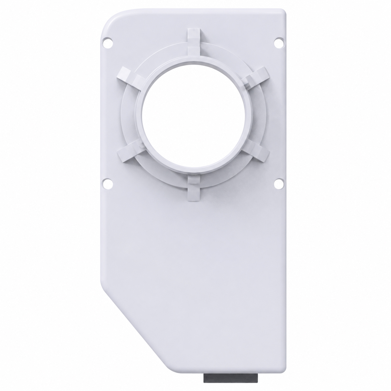
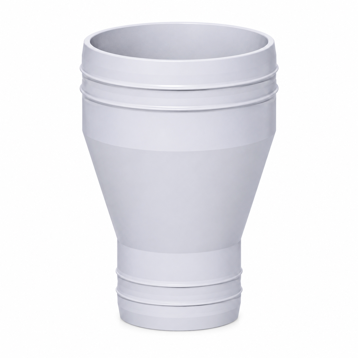
The External Exhaust System does not guarantee that all odor will be eliminated. Higher airflow is not always better. Excessive crossflow may affect the ink droplet trajectory and reduce print quality, especially when the printhead is farther from the print surface, such as when printing phone cases or other objects with a larger height difference.
The normal operating airflow is 5 L/s (10.6 CFM), measured at the external exhaust port. Do not exceed 10 L/s (21.2 CFM) at that port. If print quality becomes worse after the system is connected, pause printing and reduce the external airflow before continuing.
¶ External Exhaust Kit
Before installation, check that all materials are complete. If any material is missing, a structural component is damaged, or an interface dimension does not match, stop the installation and contact Morpho Support before proceeding.
| Item | Quantity | Notes |
|---|---|---|
| External exhaust adapter cover | 1 | Cover-style housing model. Exhaust port outer diameter: 63.5 mm (2.5 in). |
| Reducer adapter | 1 | 63.5 mm (2.5 in) to 100 mm (4 in) adapter. For another adapter size, use the OpenSCAD model to generate a compatible part. |
| 63.5 mm (2.5 in) exhaust duct and 100 mm (4 in) exhaust duct | As needed | For direct outdoor discharge, two hose sections are recommended. For connection to a filtration unit, one hose section is recommended. Keep the total duct length between 1 m and 2 m unless the connected equipment specifies otherwise. |
| Hose clamp and tightening screw | As needed | Four clamps are recommended for direct outdoor discharge. Two clamps are recommended for connection to a filtration unit. |
| M5 × 10 ST self-tapping screw | 4 | Used to secure the external exhaust adapter cover. |
| Phillips screwdriver | 1 | Used to tighten the fixing screws. |
| Item | Specification |
|---|---|
| External exhaust port | Nominal outer diameter: 63.5 mm (2.5 in) |
| Compatible hose | Nominal inner diameter: 63.5 mm (2.5 in) |
| Total duct length | Recommended range: 1 m to 2 m |
| Adapter or reducer | Allowed only when the user confirms that the adapter, hose, clamps, and connected fan or filtration unit are compatible. |
¶ Difficulty and Preparation
Difficulty: ⭐⭐
Estimated time: 10–20 minutes
Prepare a clean table for removed covers, screws, and hose clamps so that small parts are not lost.
¶ 1. Turn Off and Isolate the Equipment
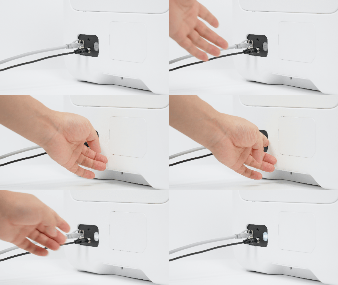
- Stop any print job.
- Turn off the printer and disconnect it from power.
- Turn off and disconnect the external fan or filtration unit.
- Wait until the printhead, fans, and all other moving parts have stopped completely.
- Clear the area around the right-side installation position.
Caution
Do not install or remove the External Exhaust System while the printer is running, the printhead is moving, or a fan is rotating.
¶ 2. Confirm the Exhaust Destination
Decide the complete exhaust route before installation. Confirm the duct length, filtration unit position, fan direction, and final exhaust destination before connecting the printer.
Available connection methods include:
- A compatible powered filtration unit.
- A compatible external exhaust fan connected to an approved exhaust path.
When exhausting outdoors, comply with local regulations, property management requirements, and building exhaust requirements. Do not direct exhaust toward people, occupied areas, air-conditioner return vents, or other sensitive locations.
¶ 3. Confirm the Airflow
Set the external airflow to 5 L/s (10.6 CFM) for normal operation and do not exceed 10 L/s (21.2 CFM), measured at the external exhaust port.
If the connected fan or filtration unit cannot be adjusted or its airflow cannot be verified, contact Morpho Support before printing with the External Exhaust System.
Caution
If print quality becomes worse after the External Exhaust System is connected, pause printing and reduce the airflow first. Do not compensate for excessive airflow by changing print settings before checking the exhaust system.
¶ Installation Steps
¶ Step 1: Remove the Right-Side Exterior Panel
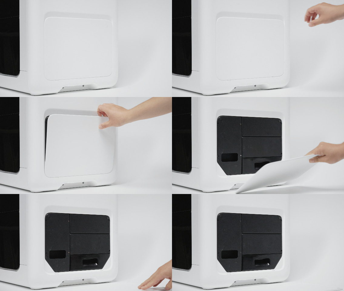
Remove the right-side exterior panel by hand. Place it on a clean surface to avoid scratches or loss.
After removal, the reserved installation area on the right side should be visible.
¶ Step 2: Remove the Activated Carbon Housing Cover and Activated Carbon
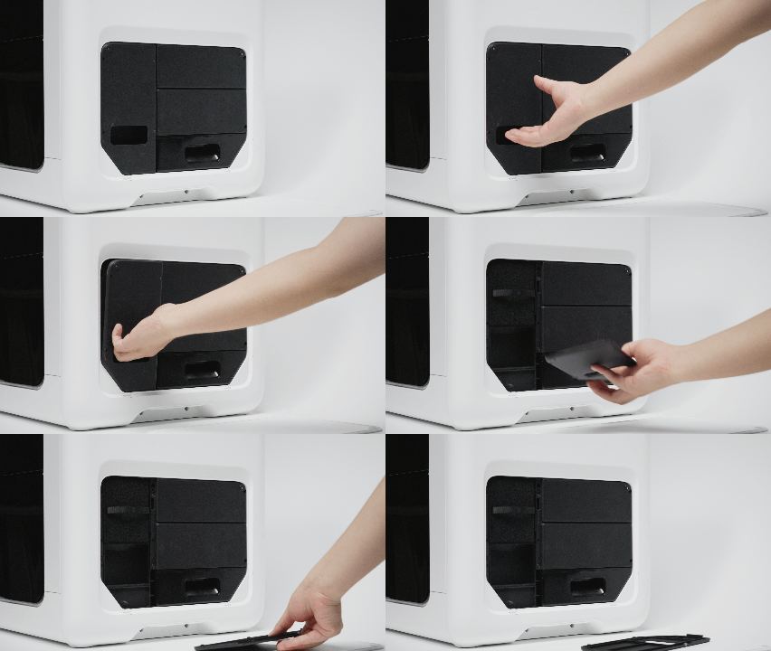
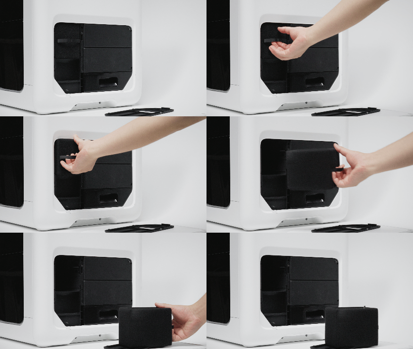
Remove the activated carbon housing cover by hand and take out the activated carbon. Confirm that the mounting base for the external exhaust adapter cover is exposed and free of foreign objects.
Caution
Do not operate the printer with the activated carbon removed unless the External Exhaust System is fully installed and the connected fan or filtration unit is operating.
If dust, debris, or another foreign object is present around the cover or mounting base, clean the area before continuing.
¶ Step 3: Install the External Exhaust Adapter Cover
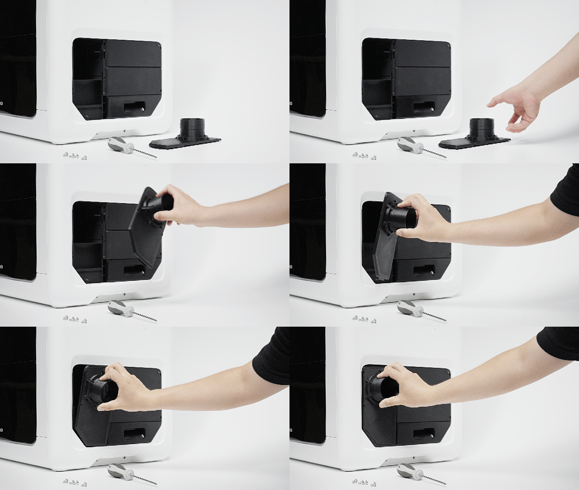
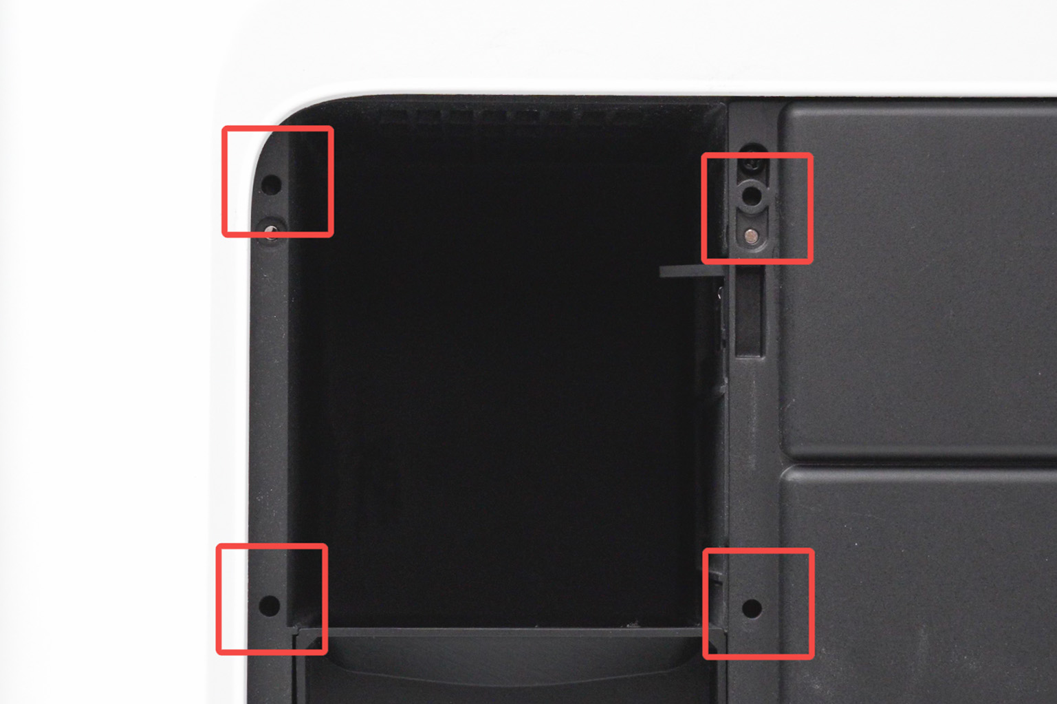
Align the external exhaust adapter cover with the activated carbon housing base. Gently press the adapter cover into place and confirm that the positioning structure is seated.
The screw holes should align naturally after the adapter cover is seated. If the holes do not align, do not force the screws. Remove the adapter cover and align it again.
¶ Step 4: Tighten the Four Fixing Screws
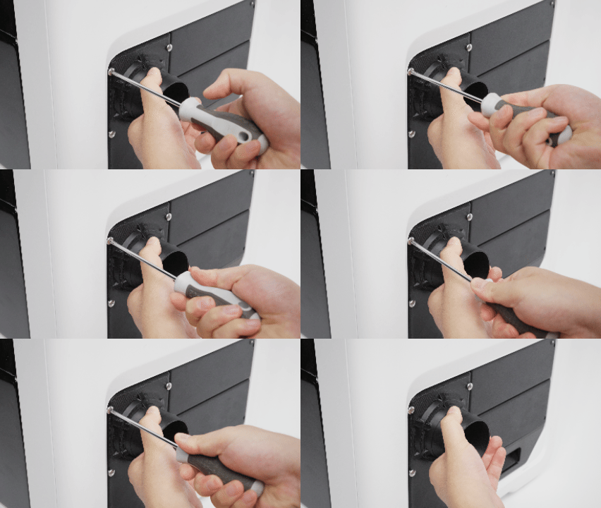
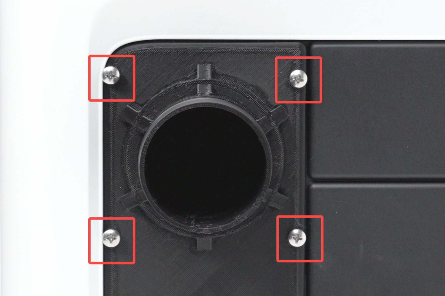
Start all four fixing screws by hand. Confirm that each screw enters smoothly, then tighten the screws one by one.
Caution
If a screw is visibly tilted, becomes increasingly tight while being turned, or the adapter cover is not flush with the mounting base, stop immediately. Check the adapter cover alignment before continuing.
¶ Step 5: Connect the Exhaust Duct and Hose Clamp
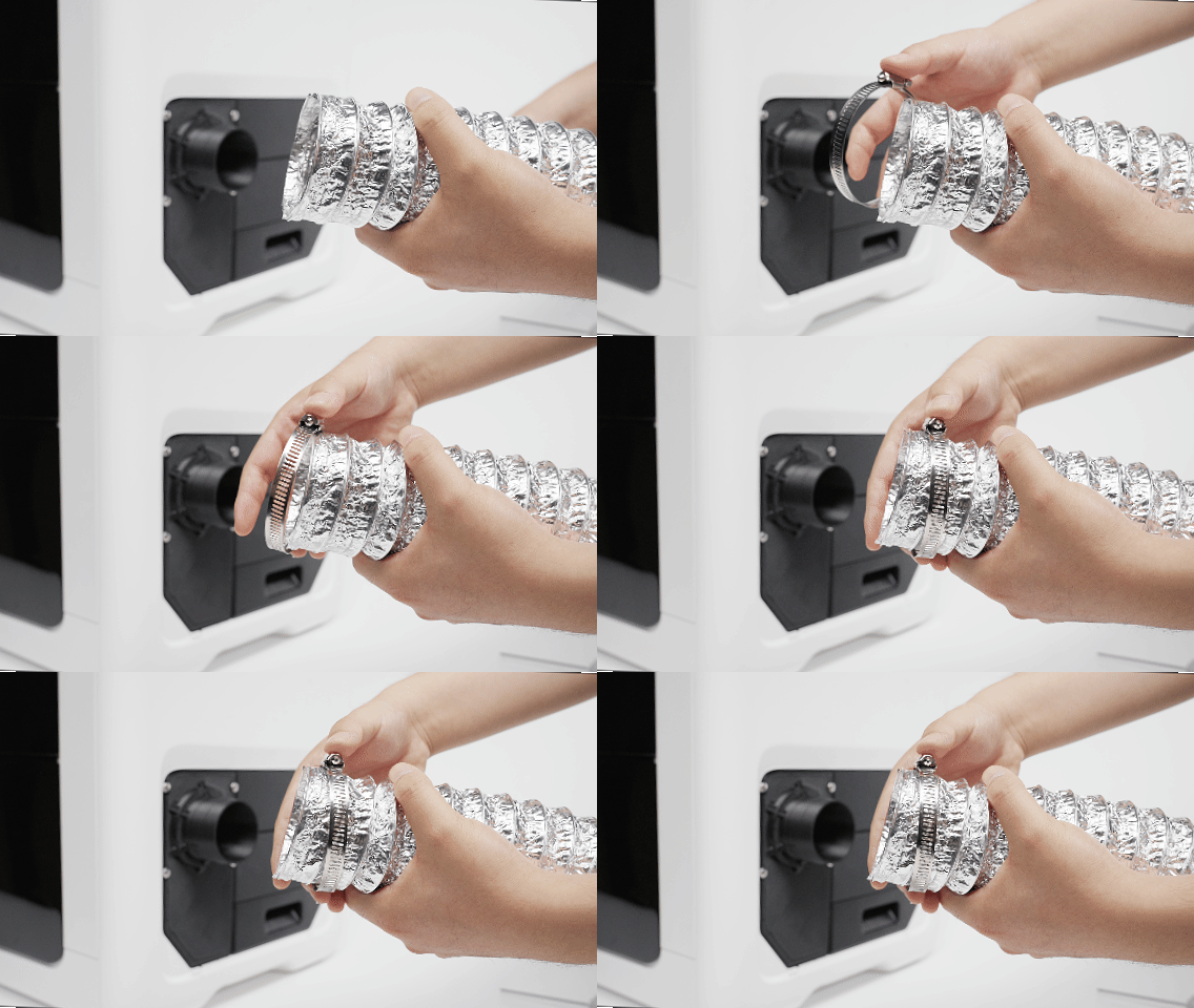
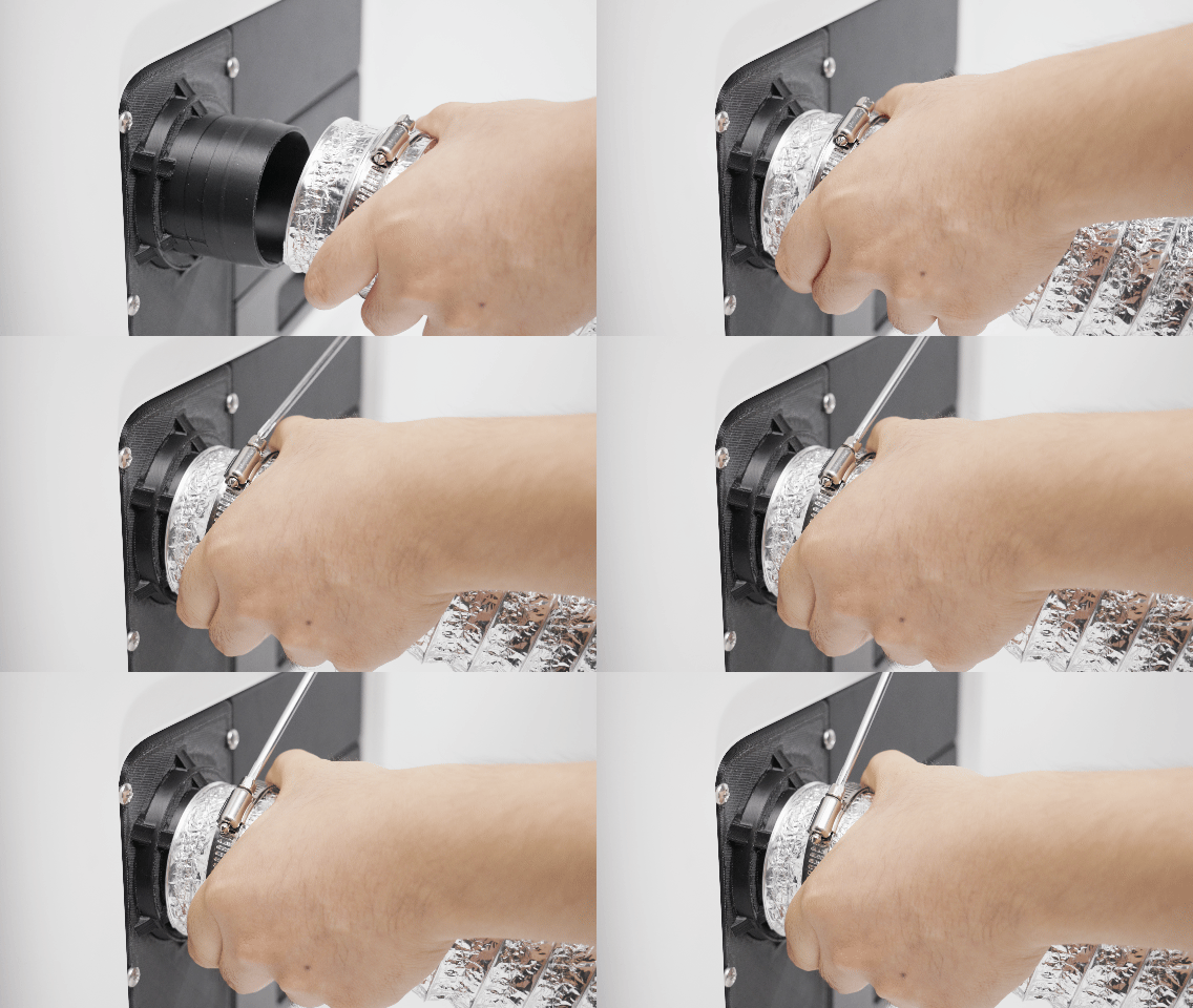
- Slide the hose clamp onto the exhaust duct.
- Insert the hose fully onto the external exhaust adapter cover port.
- Move the clamp to the port position and tighten it.
- Gently pull the hose to confirm that it does not come loose and that the clamp does not slide.
If the hose size does not match the port, use a compatible adapter. Do not force an undersized or oversized hose onto the port.
¶ Step 6: Connect the Filtration Unit or External Exhaust Fan
Before connecting the duct, check the inlet size and airflow direction of the filtration unit or external exhaust fan. Use the connection method that matches the inlet.
¶ Method A: Connect to a 63.5 mm (2.5 in) Inlet
Use this method when the filtration unit or external exhaust fan has a compatible 63.5 mm (2.5 in) inlet.
- Fit the 63.5 mm (2.5 in) exhaust duct over the device inlet.
- Install a compatible hose clamp and tighten it securely.
- Gently pull the duct to confirm that the connection is secure.
- Confirm that the duct is not bent, crushed, stepped on, or blocked.
¶ Method B: Connect to a 100 mm (4 in) Inlet with a Reducer
Use this method when the filtration unit or external exhaust fan has a compatible 100 mm (4 in) inlet.
Required parts:
| Item | Specification |
|---|---|
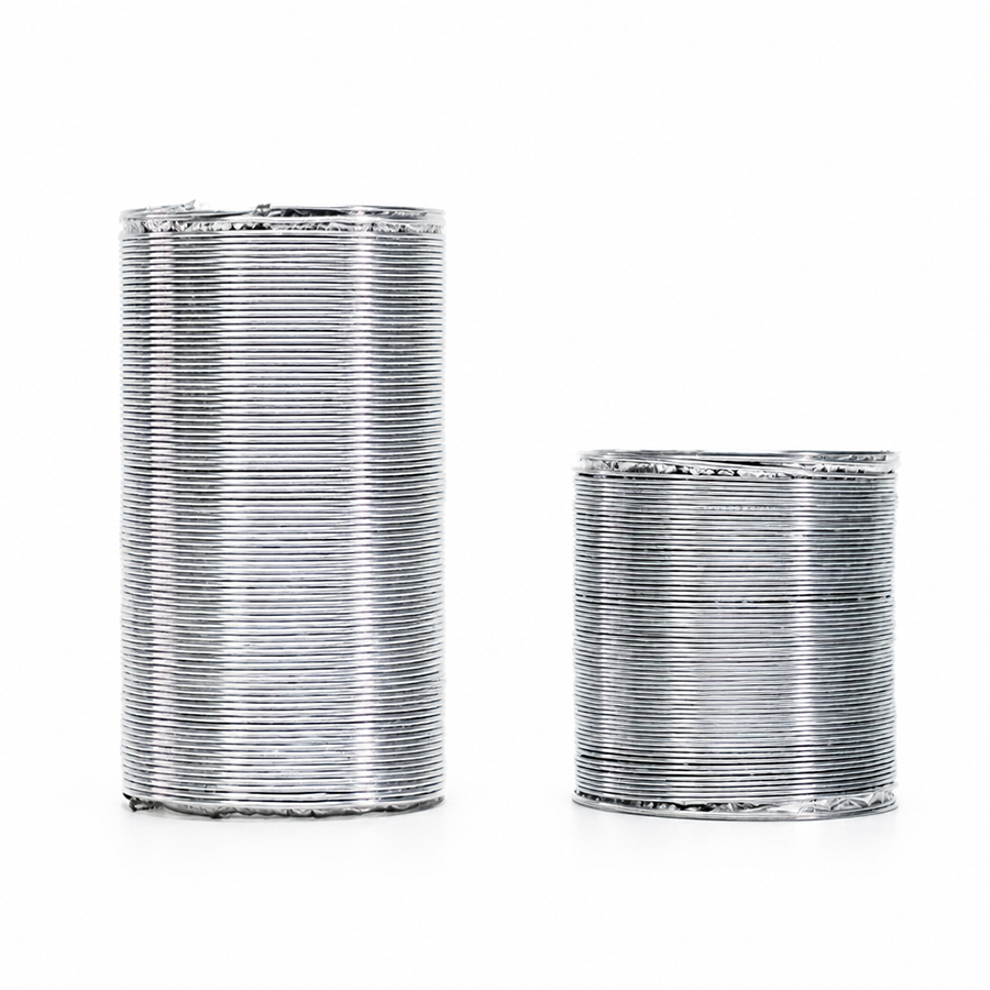
| Exhaust ducts | One 63.5 mm (2.5 in) duct and one 100 mm (4 in) duct |
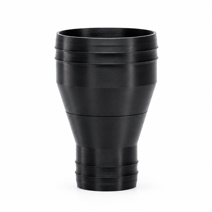
| Rigid reducer | 63.5 mm (2.5 in) to 100 mm (4 in) |
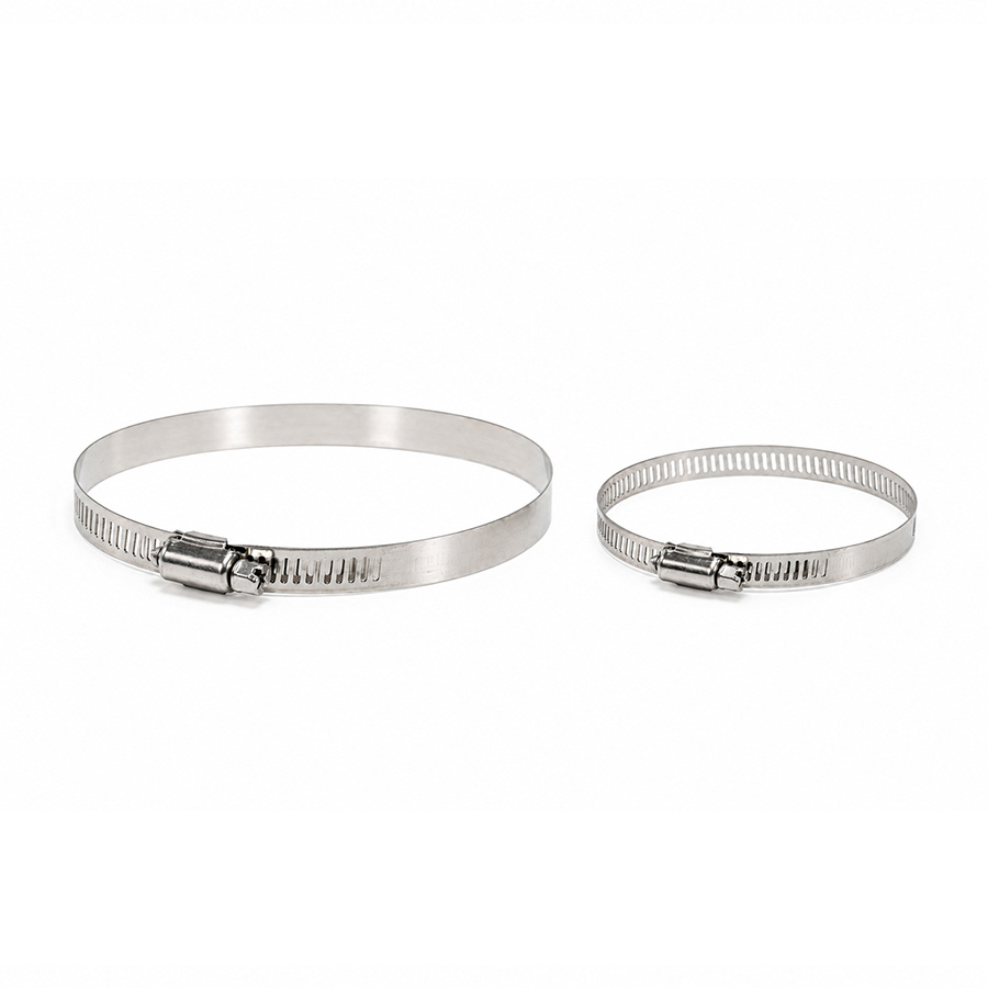
| Hose clamps | Clamps that match both duct sizes |
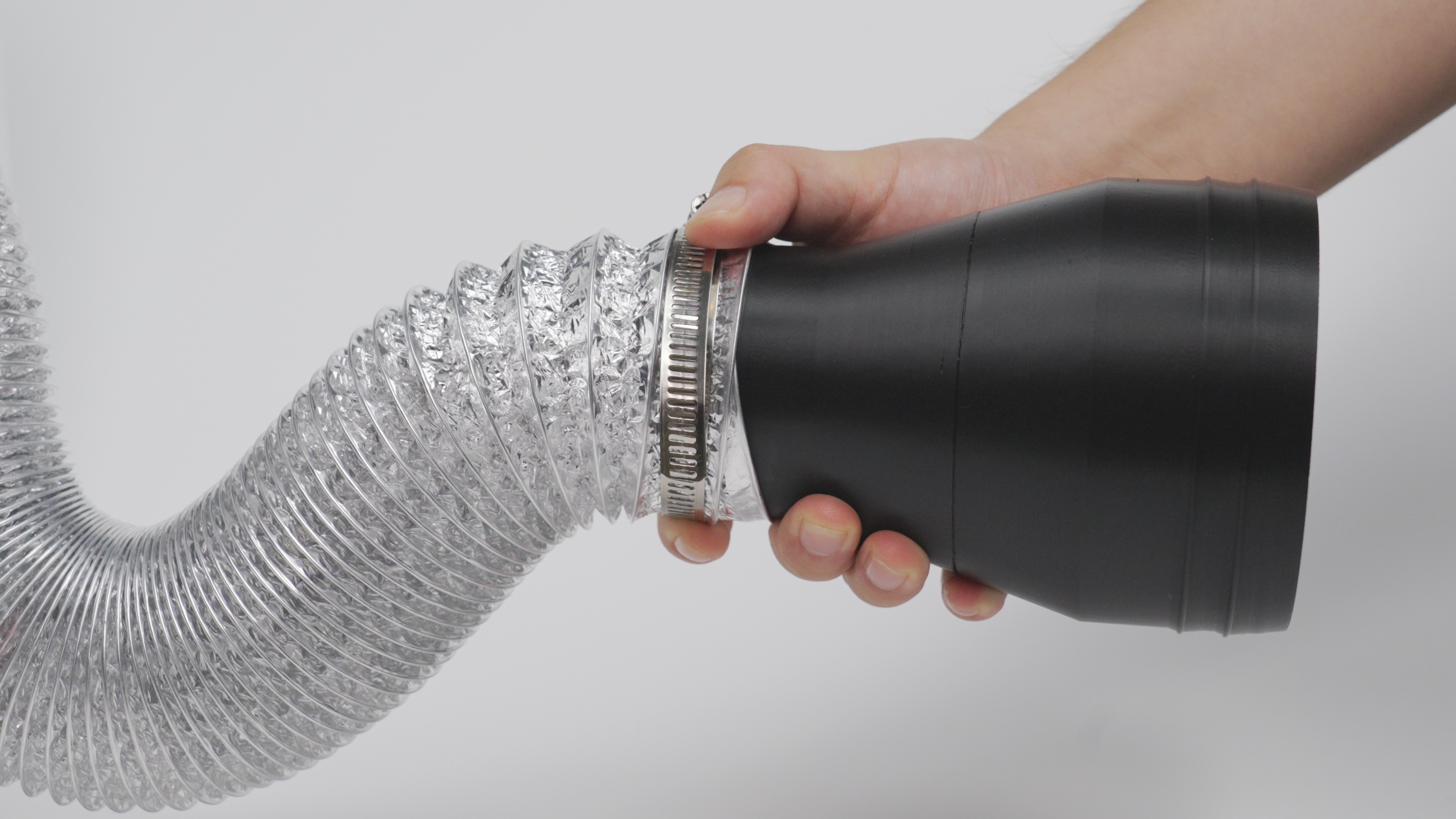
-
Connect the 63.5 mm (2.5 in) duct to the reducer and secure it with a matching clamp.
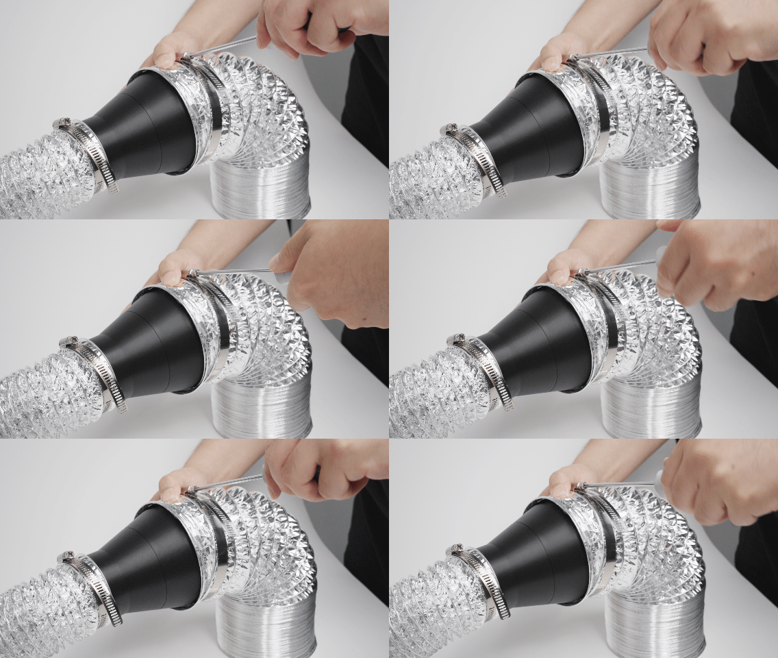
-
Connect the 100 mm (4 in) duct to the reducer and secure it with a matching clamp.
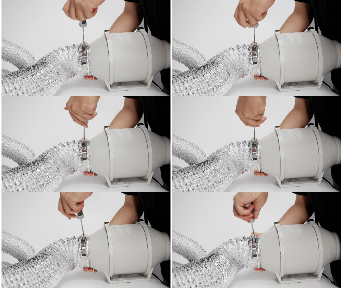
-
Connect the other end of the 100 mm duct to the filtration unit or external exhaust fan inlet, then secure it with a hose clamp.
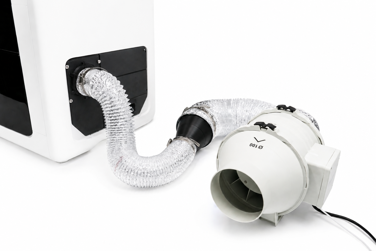
-
Check all three connection points. Confirm that the clamps are tight and that the ducts are not loose, bent, crushed, or blocked.
¶ Step 7: Complete the Connection for Your Device
¶ External Exhaust Fan for Outdoor Discharge
After completing Step 6, confirm that the duct is connected to the fan inlet.
If outdoor discharge is permitted for your installation:
- Connect a second duct to the fan outlet.
- Secure the connection with a suitable hose clamp.
- Secure the other end at the approved discharge location.
- Confirm that the fan inlet and outlet are oriented correctly and that all ducts are secure and free of bends or blockages.
¶ Filtration Unit
After completing Step 6, connect the duct to the filtration unit inlet.
- Secure the connection with a suitable hose clamp.
- Gently pull the duct to confirm that it is secure.
- Confirm that the duct is not bent, crushed, stepped on, or blocked.
- Follow the filtration unit manufacturer's instructions for the outlet air and filter replacement. Do not assume that filtered air is safe to discharge into an occupied room.
¶ Step 8: Secure the Exhaust End
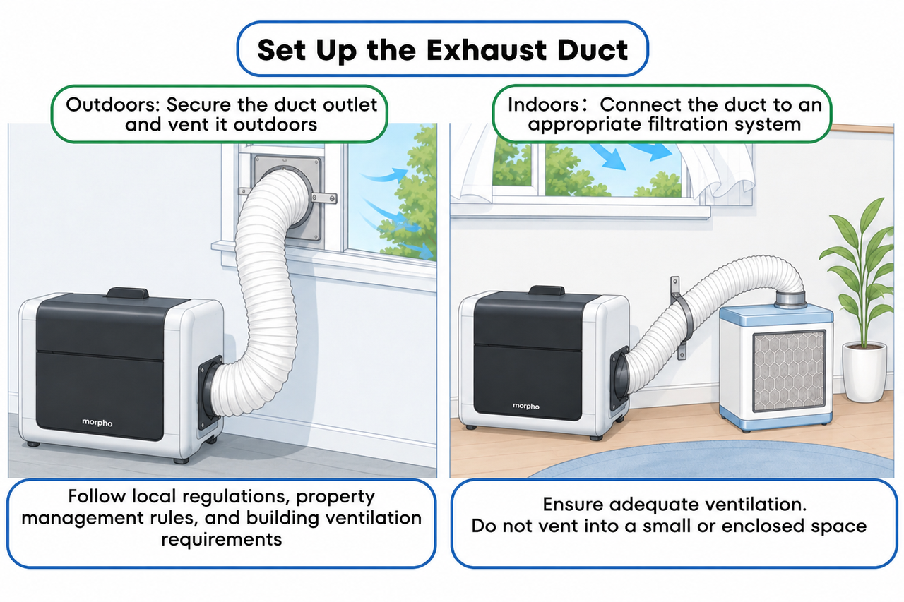
Secure the exhaust end to prevent it from swinging, coming loose, or pointing toward an unsuitable location during operation.
Caution
Keep the exhaust end away from people, pets, air-conditioner return vents, fire sources, and other sensitive locations. Do not exhaust into a small enclosed space.
¶ Step 9: Start the System and Check for Air Leakage
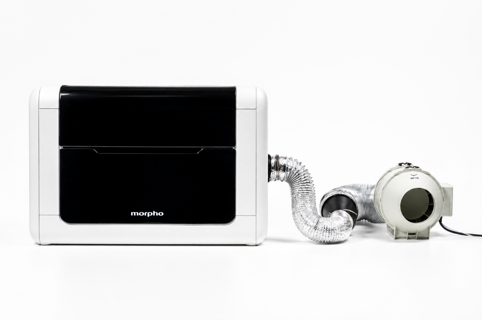
- Start the external fan or filtration unit.
- Check the connection between the adapter cover and exhaust duct.
- Check the connection between the hose and filtration unit.
- Check the connection between the hose and fan.
- Confirm that the exhaust end remains secured.
If there is obvious air leakage, turn off the fan or filtration unit, reinsert the hose, and tighten the hose clamp. Do not continue printing until the leak is corrected.
¶ How to Use the External Exhaust System
¶ Before Printing
Confirm that the exhaust duct and exhaust end are secured. If a filtration unit is connected, confirm that the hose is connected to the filtration unit inlet. Start the external fan or powered filtration unit before starting the print.
¶ During Printing
Keep the external fan or powered filtration unit running during printing. Do not step on, pinch, or pull the exhaust duct.
If the hose comes loose, abnormal noise occurs, or print quality changes, pause printing and check the installation and airflow before continuing.
¶ After Printing
Keep the external fan or filtration unit running for at least one minute after printing ends. Wait at least one minute before opening the printer cover. If odor remains noticeable, continue ventilation and follow the troubleshooting steps below.
¶ Long Periods of Non-Use
If the printer will not be used for a long period, remove the External Exhaust System and store the exhaust duct, hose clamps, adapter cover, and removed printer components in a clean, dry location.
¶ Troubleshooting
¶ Noticeable Odor
Check the following items in order:
- Confirm that ink recommended for the printer is being used.
- Check for air leakage at the adapter cover, exhaust duct, hose clamps, and filtration unit or fan connections.
- Confirm that indoor exhaust is connected to a suitable filtration unit.
- Confirm that the fan or filtration unit is operating normally and that the airflow is within the recommended range.
- Check for other possible odor sources in the room.
¶ Reduced Airflow
Check whether the duct is squeezed, kinked, stepped on, pinched, or blocked. Then check whether the filtration unit or fan inlet is blocked and whether the fan is operating normally.
¶ Increased Noise
Check whether the user-supplied fan is securely fixed and whether it has abnormal noise or airflow. Check whether the duct end is swinging, loose, or touching another object.
¶ Impact on Print Quality
First reduce the external airflow. Then check whether the duct is leaking, loose, or creating abnormal airflow across the print area. Do not exceed 10 L/s (21.2 CFM) at the external exhaust port.
¶ Maintenance Recommendations
| Item | Recommended interval | Inspection content |
|---|---|---|
| Hose inspection | Once per week | Check whether the exhaust duct is loose, kinked, damaged, blocked, or pinched. |
| Seal inspection | Once per week | Check for air leakage at the adapter cover, hose clamps, and duct connections. |
| Filtration unit inspection or replacement | Follow the selected filter's specification sheet | Maintain and replace the filter according to the filtration unit manufacturer's instructions. |
¶ When to Contact Morpho Support
Contact Morpho Support if any of the following occurs:
- The External Exhaust System cannot be installed, removed, or restored.
- Print quality is clearly affected after the External Exhaust System is connected.
- Odor remains strong after the installation and troubleshooting checks are complete.
- The adapter cover, screw holes, hose clamps, or exhaust ports are damaged.
When contacting Support, include:
- A photo of the adapter cover installation position;
- A photo of the connection between the exhaust duct and hose clamp;
- A photo of the filtration unit or fan connection;
- A photo of the secured exhaust end;
- A description of the airflow setting and the connected fan or filtration unit.
¶ Related Documents
¶ FAQ
¶ Can the External Exhaust System Completely Eliminate Odor?
No. Complete odor or emission removal cannot be guaranteed. The system routes air from the print chamber to a compatible filtration unit or approved exhaust path and should be used together with appropriate room ventilation and the connected equipment's instructions.
¶ Is a Filtration Unit Required?
A filtration unit may not be required only when outdoor discharge is permitted and the exhaust path complies with applicable local requirements. For indoor exhaust, use a filtration unit that is suitable for the expected airflow and contaminants. Follow the filtration unit manufacturer's instructions for the outlet air and filter replacement.
¶ Why Shouldn't the Airflow Be Set as High as Possible?
Excessive crossflow may affect UV ink droplet trajectory and reduce print quality. This effect may be more noticeable when the printhead is farther from the print surface, such as when printing phone cases or other objects with a larger height difference.
¶ What Is the Relationship Between 2.5 in and 63.5 mm?
2.5 in is approximately equal to 63.5 mm. In this guide, 2.5 in / 63.5 mm refers to the nominal interface specification. Confirm the actual compatible size against the manufactured parts and connected equipment.
¶ Can the System Exhaust Into a Small Enclosed Space?
Exhausting into a small enclosed space is not recommended. If the system is used indoors or in a relatively enclosed space, use a suitable filtration unit, keep the room ventilated, and follow the filtration unit manufacturer's instructions.