¶ Base Plate Structural Design (A4 and A3)
This page is intended for makers and third-party accessory developers. It explains how to develop jigs, fixtures, positioning trays, and small-batch production aids based on the Morpho UV Printer base plate and A3 Printbed.
These resources are provided to help developers understand mounting points, locating holes, the coordinate system, and reference geometry. They are not intended for copying, manufacturing, or selling the original Morpho base plate itself.
¶ Open Scope
You may use these resources to develop self-made jigs, third-party fixtures, repeatable positioning trays, and themed production aids. You may also refer to the demo jigs in this folder when designing batch-printing solutions for specific objects.
Do not describe third-party jigs as original Morpho parts. Do not use a jig for batch production without real-machine validation. Do not allow any jig to enter the safety clearance zones of the printhead, sensors, motion system, or locking mechanism.
¶ Platform References
| Parameter | Base plate | A3 Printbed |
|---|---|---|
| Applicable scenarios | Standard flat printing, self-made small jigs, regular fixture positioning | A3-format printing, large-size trays, large-area repeatable positioning jigs |
| Effective print area | 330 x 220 mm | 330 x 420 mm |
| Maximum object height | Up to 168 mm; actual usable height must subtract the jig, clamps, and local raised features | Up to 133 mm; actual usable height must subtract the jig, clamps, and local raised features |
| Planar coordinate origin | Lower-left corner | Lower-left corner |
| X / Y direction | X increases to the right; Y increases upward | X increases to the right; Y increases upward |
| Mounting / positioning method | Based on the mechanical mounting points, positioning references, and public reference geometry on the base plate | Based on the four corner locating holes, platform boundary, and public reference geometry of the A3 Printbed |
| Recommended positioning mode | Custom Jig mode / Snapshot mode | Custom Jig mode / Snapshot mode |
When developing a jig, always use the platform lower-left origin, mechanical locating holes, mounting points, and repeatable physical contact references as the design baseline. If Morpho later publishes more detailed dimension drawings, hole-position drawings, or restricted-area drawings, use the latest published drawings as the reference.
A third-party jig may cover some recognition codes or surface marks on the base plate. If that happens, use Custom Jig mode or Snapshot mode for positioning. Do not rely on blocked visual marks on the base plate.
| Base plate | 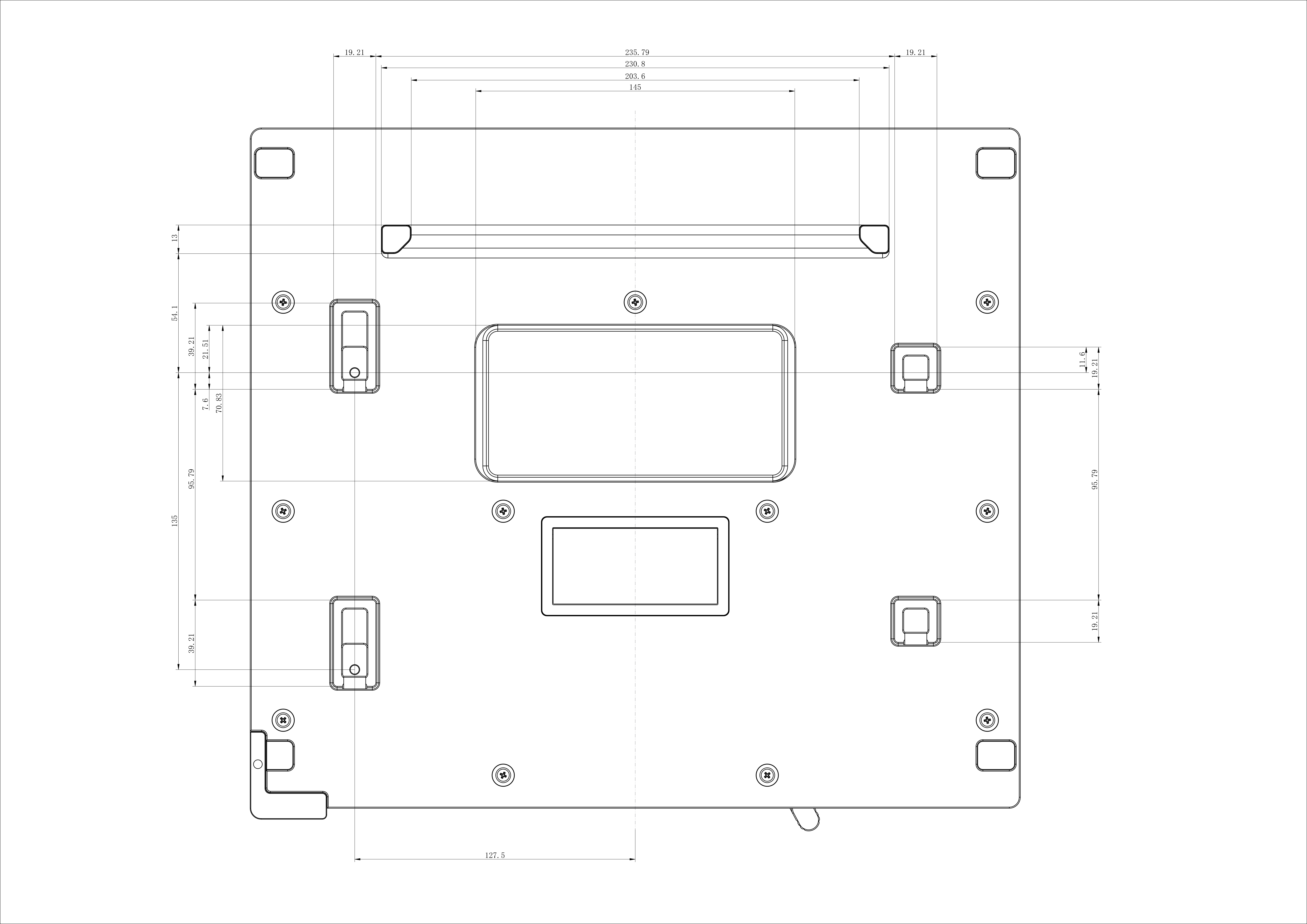 |
| A3 printbed | 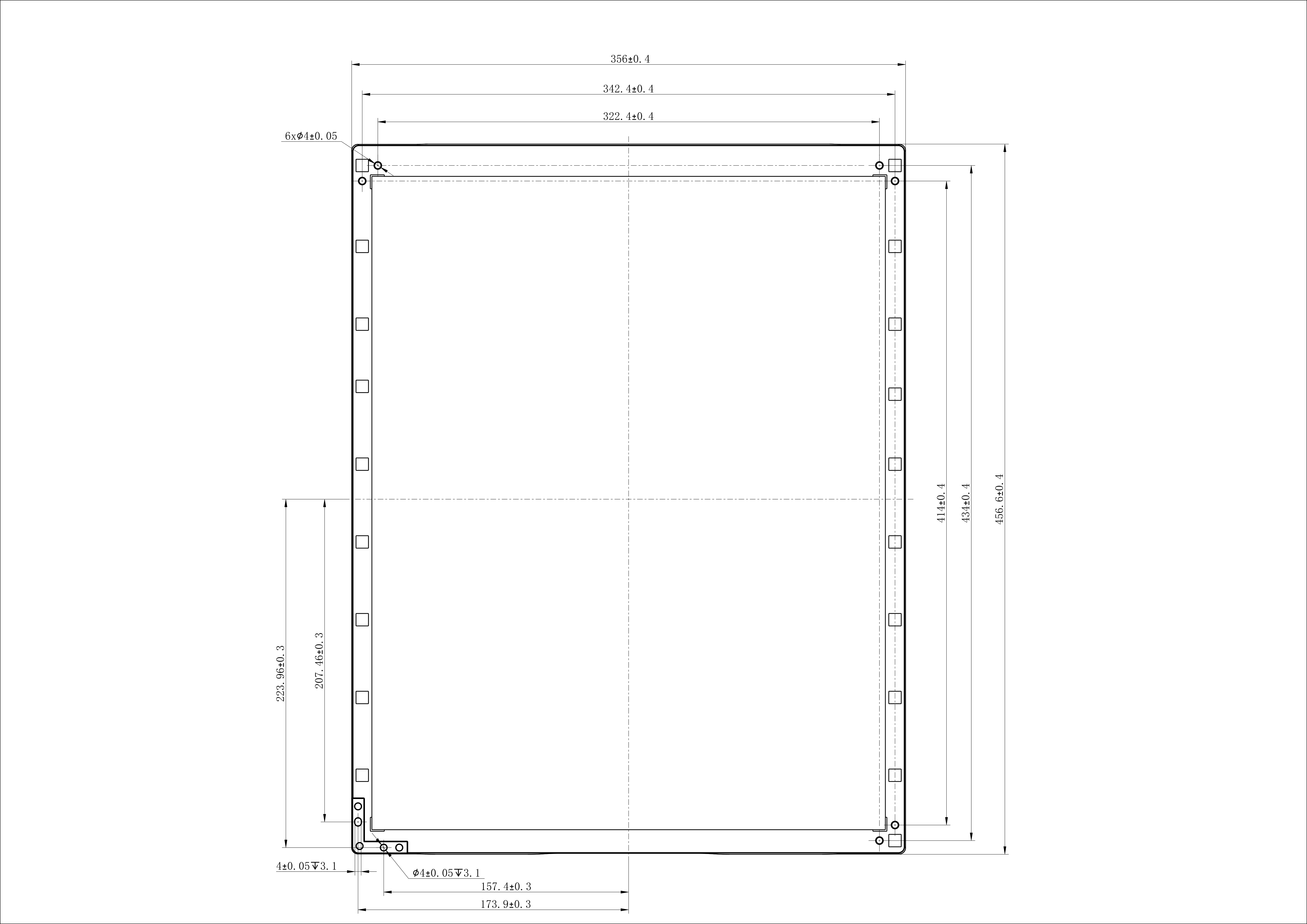 |
| base plate | BasePlate.stp |
| A4 tray printing file | a4_tray.pdf |
| A3 printbed | a3_printbed.stp |
| A3 printing file | a3_printbed.pdf |
¶ Development Workflow
| Stage | Key actions | Output |
|---|---|---|
| Select platform | Select the base plate or A3 Printbed based on print area and jig size. | The target platform and effective print range are clearly defined. |
| Build coordinates | In CAD, set the lower-left corner as the origin, define X to the right and Y upward, and align mounting points, locating holes, and platform boundaries. | The jig design is aligned with the machine coordinate system. |
| Build structure | Design object pockets, locating edges, stop surfaces, clamping structures, pickup clearance, and custom zero points. | Objects can be placed repeatedly and removed without difficulty. |
| Define areas | Define the printable area and no-print area for each object. | Accidental printing on the base plate or jig surface is avoided. |
| Check safety | Check whether the jig, clamps, cables, and highest object point meet auto-height measurement, safety clearance, and collision-prevention requirements. | The jig does not interfere with the printhead, carriage, camera, laser height measurement, or motion path. |
| Validate | Use low-cost samples to complete a dry run, auto-height measurement, Custom Jig mode / Snapshot positioning, and the first print. | Positioning parameters, artwork templates, or jig templates can be saved and reused. |
¶ Demo Jigs
| File | Description |
|---|---|
| golf balls jig | Golf-ball jig demo. Use it as a reference for positioning, clamping, and repeatable printing with multiple objects. |
| acrylic.stp | Acrylic jig demo. Use it as a reference for positioning, pickup/removal, and batch printing with sheets or small flat objects. |
The demo files only illustrate jig-development methods. They do not mean that the same structure can be directly applied to every object. Developers still need to revalidate the design according to object dimensions, material, surface shape, print area, and pickup/removal method.
¶ Safety, Warranty, and Attribution
Third-party jigs are part of the Open System expansion capability. Before use, confirm that the jig is installed correctly and firmly fixed, and that it does not interfere with the printhead, carriage, camera, laser height measurement, platform lock, or any other motion path.
Stop using the jig if it becomes loose, warped, deformed, contaminates the platform, or affects automatic height measurement.
This document only explains the base-plate interface reference method for Morpho Open System. Actual support and warranty handling are subject to Morpho's official sales terms, support policy, and after-sales assessment.
If you design, publish, or sell a third-party jig based on the resources in this folder, include the following attribution in your documentation:
Based on Morpho Open System.